English
 Español
Across the vast landscape of the power system, there are crucial "eyes." These unseen devices constantly monitor the pulses of every current flowing through the grid. They are current transformers (CTs). This seemingly simple device is the cornerstone of the safe and stable operation of high-voltage power grids and an indispensable component of measurement, protection, and control systems. They precisely convert powerful currents, up to thousands of amperes, into weak signals that can be used by secondary instruments and relays. Like the silent guardians of the power system, they faithfully fulfill their duties.
Core Principle: Ingenious Application of Electromagnetic Induction
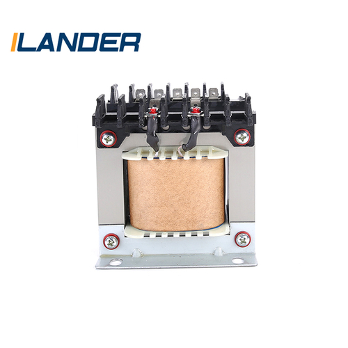
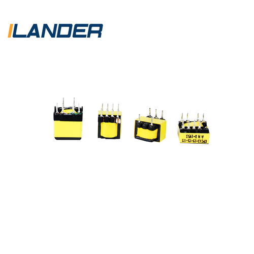
The core operating principle of a current transformer is based on Faraday's law of electromagnetic induction. Its internal structure consists of three main components: a primary winding, a secondary winding, and an iron core. When the measured current flows through the primary winding, it generates an alternating magnetic flux in the iron core. According to the principle of electromagnetic induction, this changing magnetic flux induces a voltage in the secondary winding that is proportional to the primary current. Because the secondary winding is typically connected to a low-impedance load (such as an ammeter or relay), this induced voltage generates a secondary current.
Various Varieties: Meeting the Stringent Requirements of Different Scenarios
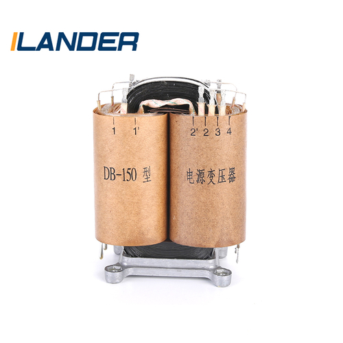
With the advancement of power technology, current transformers are becoming increasingly diverse to accommodate a wide range of complex applications. Based on the insulation medium, they can be categorized as dry-type, oil-immersed, and gas-insulated. Based on their intended use, they can be further divided into measuring, protection, and specialized types.
The core task of measuring CTs is precise measurement. They require extremely high accuracy within the normal operating current range. Key performance indicators include error, including ratio error and angle error. Ratio error reflects the deviation between the actual transformation ratio and the rated transformation ratio, while angle error describes the phase difference between the secondary and primary current phasors. To ensure accurate billing and monitoring, the design of measuring CTs must be meticulous, keeping these errors within extremely small limits.
Protection CTs are designed to operate quickly and reliably in the event of a power system fault. When an abnormality such as a short circuit occurs in the system, the current increases dramatically. In this situation, protective CTs must accurately reflect these large current fluctuations and provide a sufficiently large secondary current signal to the relay protection device to quickly clear the fault. Unlike measuring CTs, protective CTs may not require extremely high accuracy at rated current, but their performance under overload and even saturation conditions is crucial. Parameters such as the saturation point and accuracy limit factor directly determine whether the relay can properly operate under fault current.
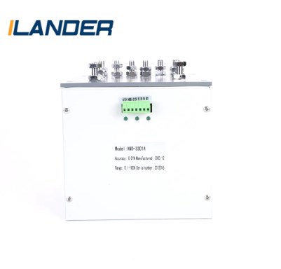
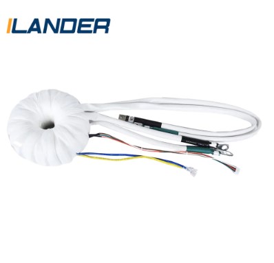
There are also current transformers designed for specialized applications, such as zero-sequence current transformers for busbar protection, which can detect single-phase ground faults by detecting the vector sum of the three-phase currents. There are also through-hole CTs used in high-voltage switchgear, whose primary winding is the high-voltage busbar itself, resulting in a compact and easy-to-install design.
Striving for Excellence: An In-Depth Analysis of Error and Saturation
In the field of current transformers, understanding error and saturation characteristics is crucial. Ratio error and angular error are two basic indicators of transformer performance. Ratio error primarily arises from the core's magnetizing current, which consumes a portion of the primary current, preventing the secondary current from fully linearly reflecting the primary current. The angular error arises from the phase difference between the excitation current and the primary current, resulting in a slight phase shift between the secondary and primary currents. To minimize these errors, engineers use high-quality core materials with high magnetic permeability and implement careful structural design to reduce the excitation current.
Saturation is a challenge that current transformers must face under extreme operating conditions. When the primary current is excessive, exceeding the core's magnetizing capacity, the core enters a saturated state. Upon saturation, the core's magnetic permeability drops sharply, the proportional relationship between the secondary and primary currents becomes non-linear, and the current conversion ratio changes significantly. For measuring CTs, saturation outside the normal operating range can lead to inaccurate measurement. For protective CTs, premature saturation can distort the signal provided to the relay, even preventing the protective action from being activated. This can prevent the fault from being cleared in a timely manner, causing serious damage to the power grid. Therefore, when designing protective CTs, it is important to ensure that they remain unsaturated at the maximum expected fault current or provide a reliable signal within the unsaturated range.
Technological Frontier: The Rise of Electronic Current Transformers
Although traditional current transformers are mature and reliable, their inherent limitations are becoming increasingly apparent in certain applications, such as their bulky size, sensitivity to saturation, and manufacturing difficulties in ultra-high voltage and high current environments. To overcome these challenges, the electronic current transformer (ECT) emerged.
ECTs typically employ unconventional principles such as Rogowski coils or optoelectronic technologies (such as fiber-optic current transformers based on the Faraday effect) to measure current. A Rogowski coil is essentially an ironless, air-core coil. It induces a voltage by measuring the rate of change of magnetic flux passing through it. An integrating circuit then generates an output proportional to the measured current. The absence of an iron core fundamentally eliminates saturation, resulting in a wide measurement range and a lightweight and compact design.
Fiber-optic current transformers utilize the Faraday effect, where the polarization plane of light rotates in a magnetic field. By measuring the angle of polarization rotation, the measured current can be accurately calculated. This technology offers significant advantages, including high insulation, strong resistance to electromagnetic interference, and long transmission distances. It is particularly suitable for use in ultra-high and ultra-high voltage transmission lines and represents the forefront of current transformer technology development.
From its early days of electromagnetic induction to today's electronic and fiber optic technologies, current transformers have undergone a profound evolution. From the "unsung heroes" of the power grid, they have gradually moved toward intelligent and digital capabilities. However, regardless of technological advancements, their essential mission remains the same: to provide reliable current information for the safe and stable operation of power systems. Each current transformer is a precise sensor and a reliable isolator. Together, they form a solid defense for the power system, ensuring the shining lights of countless homes and the smooth progress of industrial giants.